
DRIVE MATCHING · UPDATED OCTOBER 3, 2026
Matching a VFD to an HQD Spindle
Match the drive to the documented electrical configuration and operating conditions. A building supply voltage or a power label is only part of that check.
Keep voltage and current on the same winding.
Start with the winding specified for the supplied unit. Where the drawing documents more than one winding, choose one voltage/current pair. GDL120-30-24Z/5.5 has 220 V/19 A and 380 V/11 A configurations; 220 V with 11 A is not one of those pairs.
Check the VFD output capability, input supply arrangement and current capability with the drive documentation. A matching voltage in the spindle search does not confirm that a VFD, wiring arrangement or protective device is suitable.
Check the required output frequency and speed.
The GDL120 point is 24,000 rpm at 800 Hz, with four poles. GDK125-30Z/7.5 is documented at 30,000 rpm and 1,000 Hz. The drive must support the actual operating requirement; speed alone cannot stand in for the model-specific frequency.
The air-cooled GDL40.5 has an 18,000 rpm rated point at 300 Hz and a separate 24,000 rpm maximum at 400 Hz. Keep the rated point and maximum limit separate when checking the supplied-unit settings. Use the parameter settings specified for the exact spindle and VFD.
Read range models through their original curves.
A variable-range spindle can list voltage and frequency endpoints over its operating range. GDK100-12-24Z/2.2-4.4 documents 269–380 V over 400–800 Hz. Those endpoints describe the curve; they do not establish two separately selectable windings.
Its power curve also distinguishes S1 and S6-20% at TA20°C. Use the 2.2 kW rated output and retain the conditions for any higher curve output. Do not select a drive or claim continuous cutting power from the larger number in the code alone.
Separate auxiliary circuits and control connections.
Fan, sensor and release circuits have their own functions. The 24 V DC connections on the GDL40.5 drawing serve the fan and sensors; the spindle winding is specified for 220 V. A reserved feedback connector also does not establish that an encoder is fitted.
Confirm the required control signals, sensor functions and release interlocks for the supplied configuration. Use the exact wiring drawing rather than a neighboring model or a generic connection diagram.
Prepare a drive-matching inquiry with the missing details.
Include the full spindle code and winding, the drive model, its input and output specifications, required speed range and planned duty. Add the machine control and auxiliary supply details where applicable.
If the current, winding or curve conditions are unresolved, ask for confirmation before choosing settings or finalizing the drive. Use the documents for the exact spindle and drive when setting up the installation.
- Selected winding and paired current
- Rated point, maximum or operating range
- Required frequency and documented duty
- Drive input/output capability
- Auxiliary circuits and open technical questions
Questions before you choose.
Are curve voltage endpoints winding choices?
No. Read them with the corresponding speed/frequency curve and confirm the supplied electrical configuration.
Can I power the spindle from a sensor supply?
No. Auxiliary circuits and the spindle winding are separate. Use the wiring and electrical specification for the supplied unit.
RELATED SPINDLES
Configurations discussed in this guide.
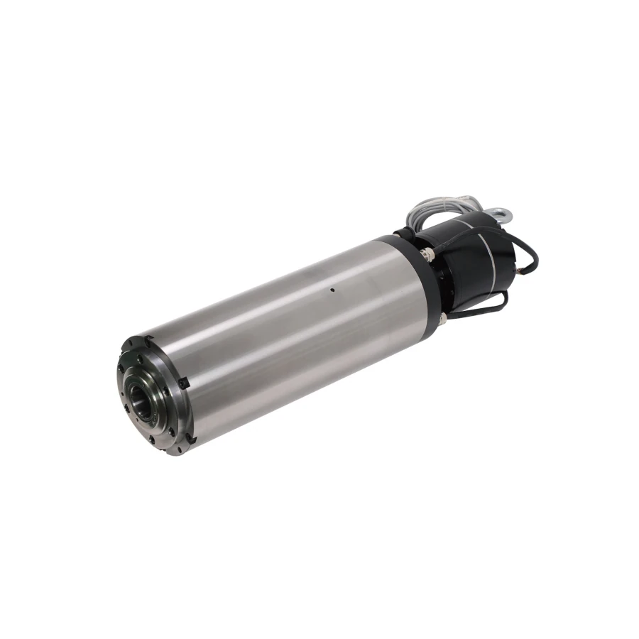
GDL · ATC
GDL120-30-24Z/5.5
5.5 kW rated · BT30
24,000 rpm rated · Water-cooled
Ø120 mm · 496.5 mm overall · 136 mm clamp
View specifications →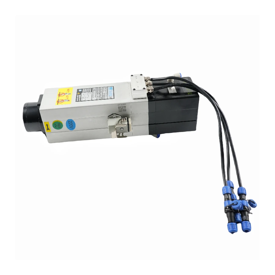
GDL · ATC
GDL40.5-ISO20-24Z/2.2
2.2 kW rated · ISO20
18,000 rpm rated / 24,000 rpm max · Air-cooled
372.5 mm overall
View specifications →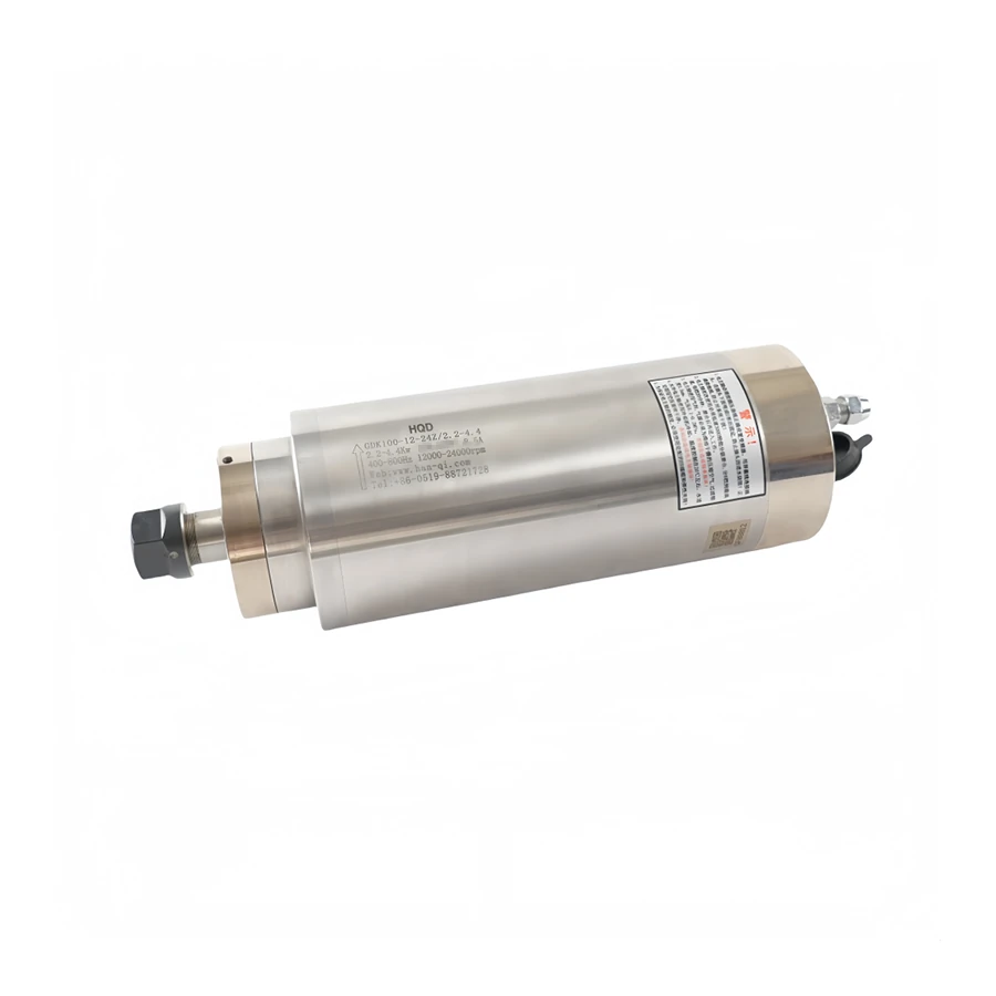
GDK · Manual
GDK100-12-24Z/2.2-4.4
2.2 kW rated · ER20
12,000–24,000 rpm · Water-cooled
Ø100 mm · 295 mm overall · 140 mm clamp
View specifications →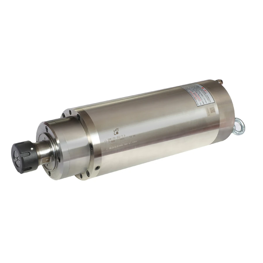
GDK · Manual
GDK125-30Z/7.5
7.5 kW rated · ER32
30,000 rpm rated · Water-cooled
Ø125 mm · 150 mm clamp
View specifications →