ATC INSTALLATION · UPDATED OCTOBER 3, 2026
What an ATC Spindle Needs from Your Machine
Automatic tool change adds a set of interfaces around the motor. Match the holder, installation, drive and release controls together before choosing a spindle.
Start with the toolholder interface.
ISO20 and BT30 identify different taper interfaces. A spindle change can affect the holders, tool rack, release arrangement and clearances. An ATC label alone does not establish that the spindle will work with the machine's existing tooling.
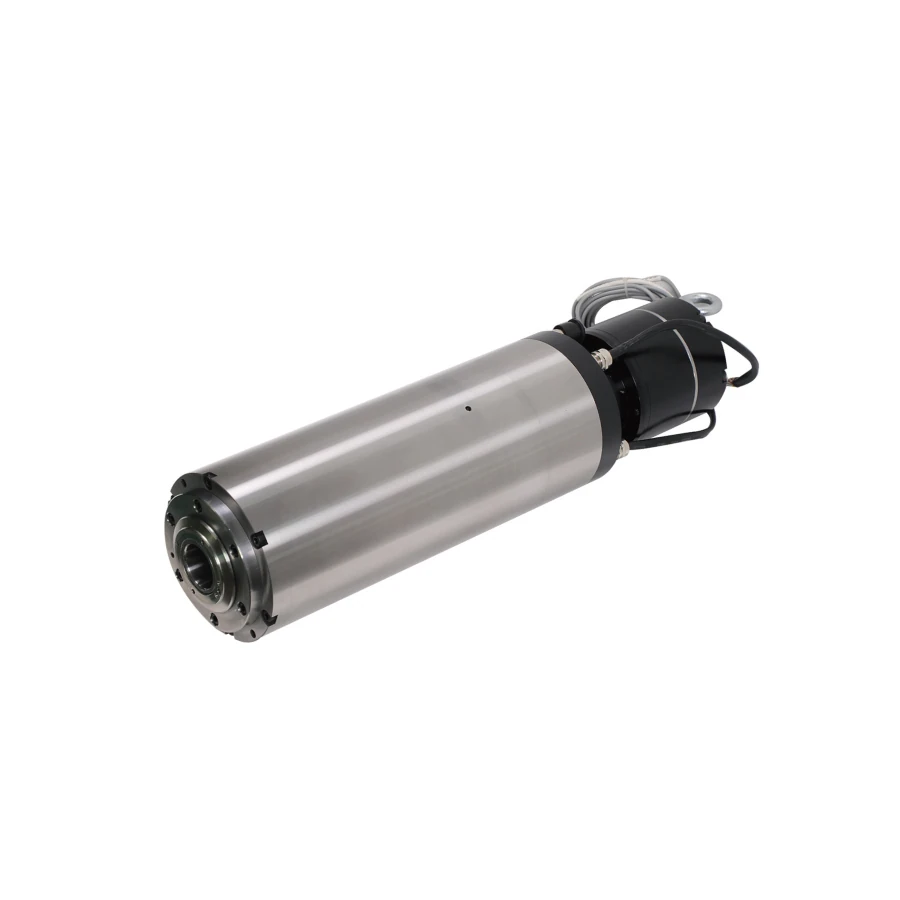
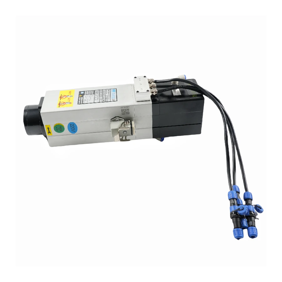
The GDL40.5-ISO20-24Z/2.2 uses ISO20. The GDL120-30-24Z/5.5 uses BT30. Treat them as different installation choices rather than alternatives selected by power alone.
Check the complete assembly envelope.
Compare the mounting arrangement, clamp dimensions, spindle nose and rear cylinder or auxiliary assembly. Include clearance for connectors, hoses and the tool-release movement.
The GDL120 drawing lists a 120 mm body, 136 mm clamping length and 496.5 mm overall length. The GDL40.5 installation includes a side auxiliary assembly. Use the exact drawing when assessing space; a body diameter or model prefix cannot describe the whole envelope.
Pair the winding with the drive settings.
The spindle's voltage, current, speed and frequency need to be checked together. Confirm the VFD output capability rather than using mains voltage as a substitute for the spindle winding specification.
For the GDL120-30-24Z/5.5, the drawings give 220 V / 19 A and 380 V / 11 A windings at 24,000 rpm and 800 Hz. Keep those values paired. The GDL40.5-ISO20-24Z/2.2 has a rated point of 18,000 rpm at 300 Hz and a maximum of 24,000 rpm at 400 Hz; the maximum is a separate limit.
Auxiliary circuits are separate. The 24 V DC fan and sensor connections on the GDL40.5 drawing do not power the spindle winding, which is specified for 220 V.
Confirm air, cooling and sensing requirements.
Check the pneumatic connections and the clamp/release sequence with the machine's control system. Confirm required pressure, flow, sensor function and interlocks from documentation for the supplied configuration. Do not infer these details from another model.
Cooling must also match the installation. An air-cooled spindle still needs unobstructed airflow and the correct fan connection. A water-cooled spindle needs a suitable circuit and the specified connections.
A reserved encoder connection is not evidence of an installed encoder. Ask which sensors and feedback hardware are included before planning the wiring.
Put the installation checks into the inquiry.
- Identify the exact model, winding and toolholder interface.
- Compare the mounting drawing and complete assembly clearances.
- Check VFD output, current capability and speed/frequency settings.
- Confirm cooling, pneumatic supply and control signals.
- State the existing machine configuration and any open questions.
Use the dimensional PDF for installation checks. For CAD or additional drawings, include the exact model and configuration in your inquiry.
Prepare an InquiryRELATED SPINDLES